Application & Technical Notes
Introduction
Being solid state devices, Light Emitting Diode (LED) Lamps have inherent characteristics assuring high reliability and a compatibility with low current electronic drive circuits.
Below is technical and application information on ILT's NDIR Gas Sensor Light Sources. This Web page contains a selection of our most common LEDs. Many of our lamps can be purchased right from our e-store. If your requirement is for a different LED, please contact us for assistance using the form below.

Introduction
LEDs have advantages and disadvantages when compared with other light sources such as incandescent or neon lamps.
The advantages are small size, low power consumption, low self-heating, high reliability, they can be switched on and off quickly, and they are resistant to shock and vibration.
The features that sometimes can be considered disadvantages are the narrow viewing angle, near monochromatic light, limited wavelength selection, and they require a limiting resistor with a voltage drive.
Principles of Operation
LEDs are formed from various doped semiconductor materials in the form of a P-N diode junction. When electrical current passes through the junction in the forward direction, the electrical carriers give up energy proportional to the forward voltage drop across the diode junction which is emitted in the form of light. The amount of energy is relatively low for infrared or red LEDs. For green and blue LEDs which are produced from higher forward voltage materials, the amount of energy is greater.
Since the device is being used in the forward biased mode, once the voltage applied exceeds the diode forward voltage; the current through the device can rise exponentially. Very high currents would damage the device which is why a current limiting resistor must be added in series with the LED when driven from a voltage source.
The amount of light emitted by an LED is proportional to the amount of current passing through the device in the forward bias direction. As the current is varied, the output of the light will vary in a similar fashion. By modulating the current flowing through the LED, the light output can be modulated to produce an amplitude modulated optical signal which can be used to communicate in- formation through free space (i.e. TV remote control).
If the voltage source is applied in the reverse direction, the P-N junction will block current flow until the voltage applied exceeds the devices ability to block the current. At that point, the device junction will break down, and if there is no current limit device in the circuit, the LED will be destroyed. The typical value of maximum reverse voltage is five volts.
Construction and Operation
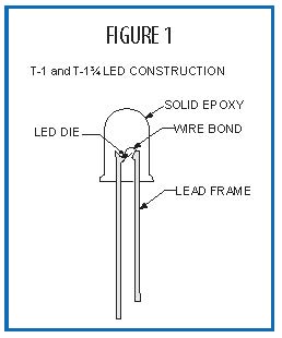
The semiconductor material is typically a very small chip or die, which is mounted onto a lead frame and encapsulated in a clear or diffused epoxy. The shape of the epoxy and the amount of diffusing material in the epoxy control the light output angle of emission. Figure 1 illustrates the construction of a common LED package.
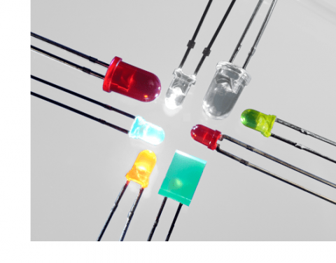
Many of our LEDs incorporate high efficiency chips mounted into T-1, T-1¾, and SMT (surface mount) packages. However, there are a wide variety of right angle, multi-package and custom packages available to meet your requirements.

The output of LEDs is typically expressed in millicandela (mcd). The candela is defined as the number of lumens per steradian of solid angle. It is usually measured along the projection axis of the device and gives the eye’s response to the light. The viewing angle for LEDs is specified as the included angle between the ½ intensity points on either side of the output beam. For T-1 and T-1¾ devices this can be as low as 10 degrees for clear epoxy devices and as high as 60 degrees for highly diffused LEDs. Peak radiation output is available ranging from the infrared through the visible down into the deep blue.
LED lamps may be operated in the pulsed mode. The absolute maximum ratings of LEDs have been determined theoretically but also from extensive reliability testing. Forward current, power dissipation, thermal resistance, and junction temperature are all interrelated in establishing absolute maximum ratings. In the pulsed mode, maximum tolerable limits should not exceed the LED junction temperature that would be reached by operating the LED at specified maximum continuous forward current. This correlation is obtained by establishing combinations of peak current and pulse width for various refresh rates and maintaining the maximum junction temperature as reached by operation at maximum continuous current.
Drive Circuits
The drive circuits for LEDs must provide sufficient voltage to overcome the forward voltage drop of the diode junction, while controlling the current to the correct value for the specific device. The most common circuit to accomplish this is a voltage source which is significantly higher than the diode forward voltage drop and a series current limiting resistor. Several configurations are shown in Figure 2. Use Ohms law to calculate the resistor value depending on the LED chosen, the voltage source, and the maximum continuous current rating.


