How Light Behaves (Chapter 3)
Reflection
Light reflecting off of a polished or mirrored surface obeys the law of reflection: the angle between the incident ray and the normal to the surface is equal to the angle between the reflected ray and the normal.
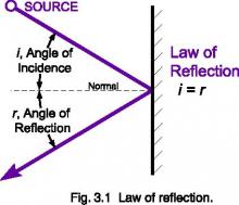
Precision optical systems use first surface mirrors that are aluminized on the outer surface to avoid refraction, absorption, and scatter from light passing through the transparent substrate found in second surface mirrors.
When light obeys the law of reflection, it is termed a specular reflection. Most hard polished (shiny) surfaces are primarily specular in nature. Even transparent glass specularly reflects a portion of incoming light.
Diffuse reflection is typical of particulate substances like powders. If you shine a light on baking flour, for example, you will not see a directionally shiny component. The powder will appear uniformly bright from every direction.
Many reflections are a combination of both diffuse and specular components. One manifestation of this is a spread reflection, which has a dominant directional component that is partially diffused by surface irregularities.


Transmission: Beer-Lambert or Bouger’s Law
Absorption by a filter glass varies with wavelength and filter thickness. Bouger’s law states the logarithmic relationship between internal transmission at a given wavelength and thickness.
log10(τ1) / d1 = log10(τ2) / d2
Internal transmittance, τi, is defined as the transmission through a filter glass after the initial reflection losses are accounted for by dividing external transmission, T, by the reflection factor Pd.
τi = T / Pd
Example:The external transmittance for a nominal 1.0 mm thick filter glass is given as T1.0 = 59.8 % at 330 nm. The reflection factor is given as Pd = 0.911. Find the external transmittance T2.2 for a filter that is 2.2 mm thick.
Solution:
τ1.0 = T1.0 / Pd = 0.598 / 0.911 = 0.656
τ2.2 = [τ1.0]2.2/1.0 = [0.656]2.2 = 0.396
T2.2 = τ2.2 * Pd = (0.396)(0.911) = 0.361
So, for a 2.2 mm thick filter, the external transmittance at 330 nm would be 36.1%
Refraction: Snell’s Law
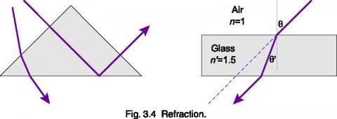
When light passes between dissimilar materials, the rays bend and change velocity slightly, an effect called refraction. Refraction is dependent on two factors: the incident angle, θ, and the refractive index, n of the material, as given by Snell’s law of refraction:
n sin(θ) = n’ sin(θ’)
For a typical air-glass boundary, (air n = 1, glass n’ = 1.5), a light ray entering the glass at 30° from normal travels though the glass at 10.5° and straightens out to 30° when it exits out the parallel side.
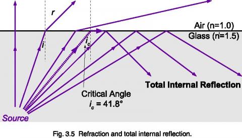
Note that since sin(0°) = 0, light entering or exiting normal to a boundary does not bend. Also, at the internal glass-air boundary, total internal reflection occurs when n’sin(θ’) = 1. This occurs at θ’ = 41.8° for n’ = 1.5 glass.
The index of refraction itself is also dependent on wavelength. This angular dispersion causes blue light to refract more than red, causing rainbows and allowing prisms to separate the spectrum.
Diffraction
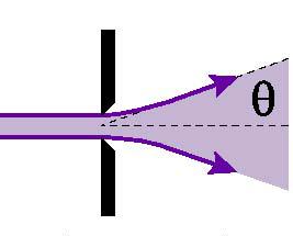
Diffraction is another wave phenomenon that is dependent on wavelength. Light waves bend as they pass by the edge of a narrow aperture or slit. This effect is approximated by:
θ = λ / D
where θ is the diffraction angle, λ the wavelength of radiant energy, and D the aperture diameter. This effect is negligible in most optical systems, but is exploited in monochromators. A diffraction grating uses the interference of waves caused by diffraction to separate light angularly by wavelength. Narrow slits then select the portion of the spectrum to be measured. The narrower the slit, the narrower the bandwidth that can be measured. However, diffraction in the slit itself limits the resolution that can ultimately be achieved.
Interference
When wave fronts overlap in phase with each other, the magnitude of the wave increases. When the wave fronts are out of phase, however, they cancel each other out. Interference filters use this effect to selectively filter light by wavelength. Thin metal or dielectric reflective layers separated by an optical distance of n’d = λ/2, or half the desired wavelength provide in phase transmission.
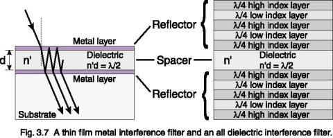
The center wavelength shifts with angle, since the optical path increases as the cosine of the angle. Special input optics are required to provide a cosine response while transmitting light through the filter at a near normal angle.

Request Light Management Handbook as PDF (ALL Chapters)
Chapter 3 - The Light Measurement Handbook
Copyright © 1997 by Alexander D. Ryer
All Rights Reserved.
No part of this publication may be reproduced or transmitted in any form or by any means, electronic or mechanical, including photocopying, recording, or any information storage and retrieval system, without permission in writing from the copyright owner. Requests should be made through the publisher.
Technical Publications Dept.
International Light Technologies
10 Technology Drive
Peabody, MA 01960
ISBN 0-9658356-9-3
Library of Congress Catalog Card Number: 97-93677
Explore more light measurement resources
